

Cleaning suction truck
Classification
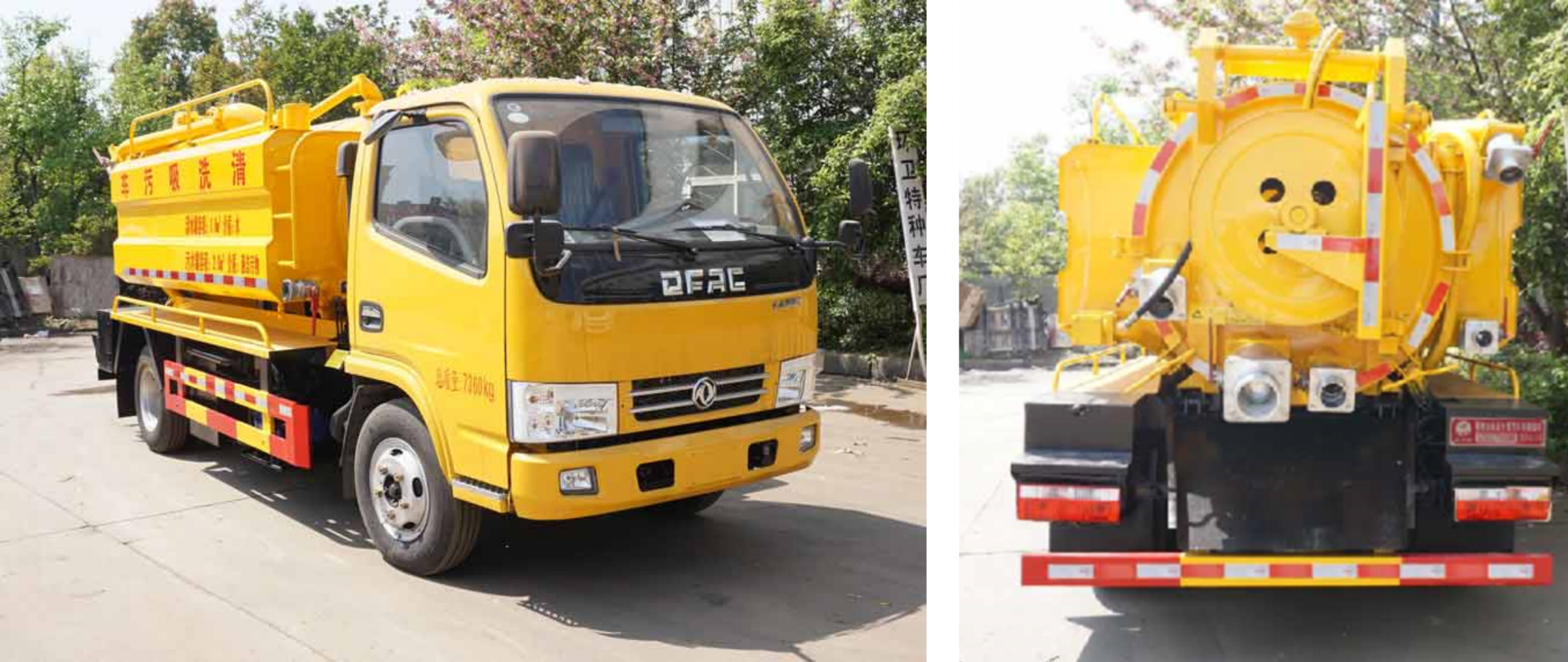
Cleaning suction truck
Product Introduction
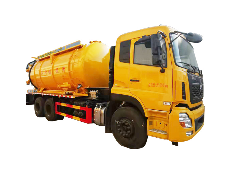


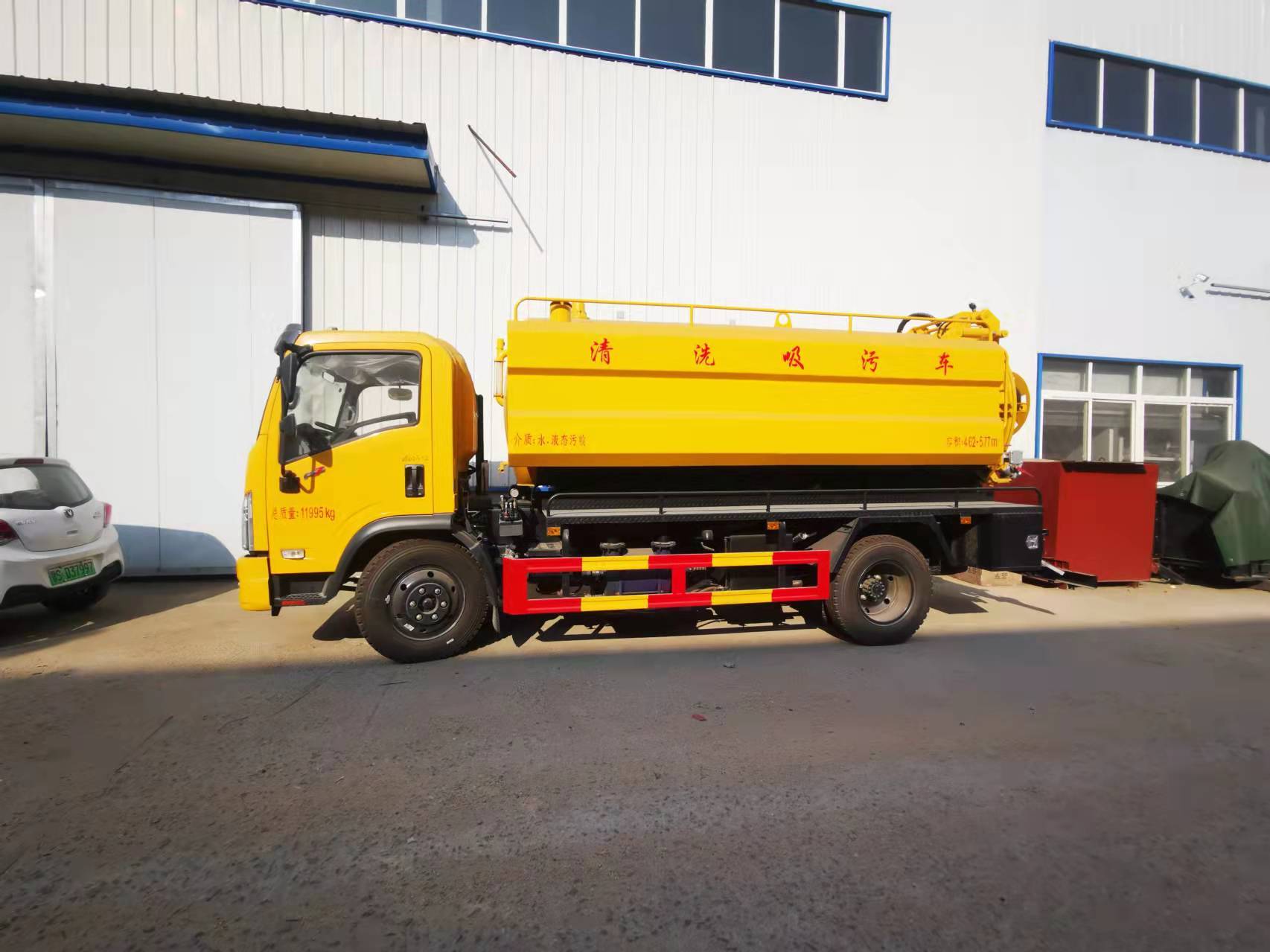
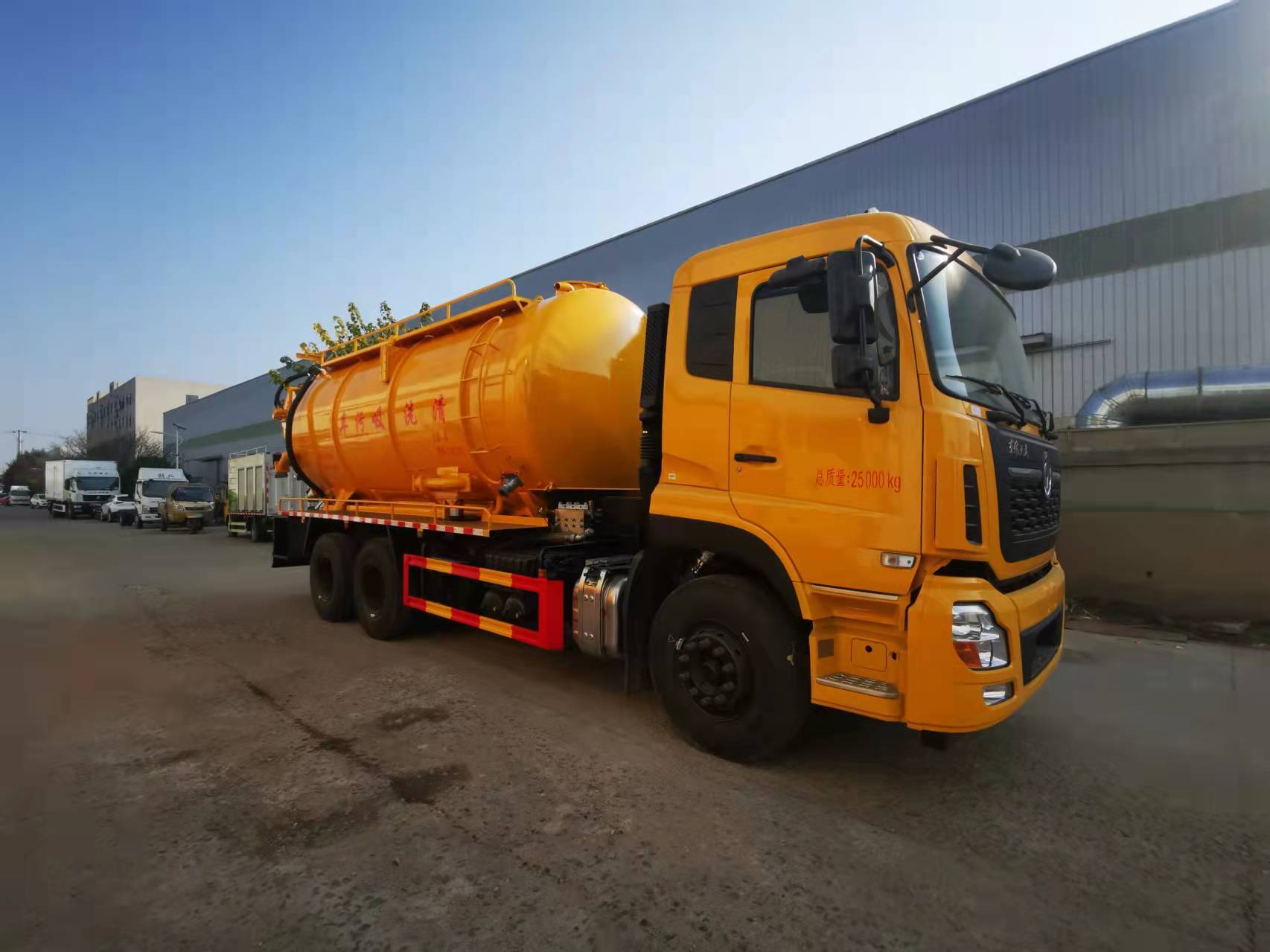

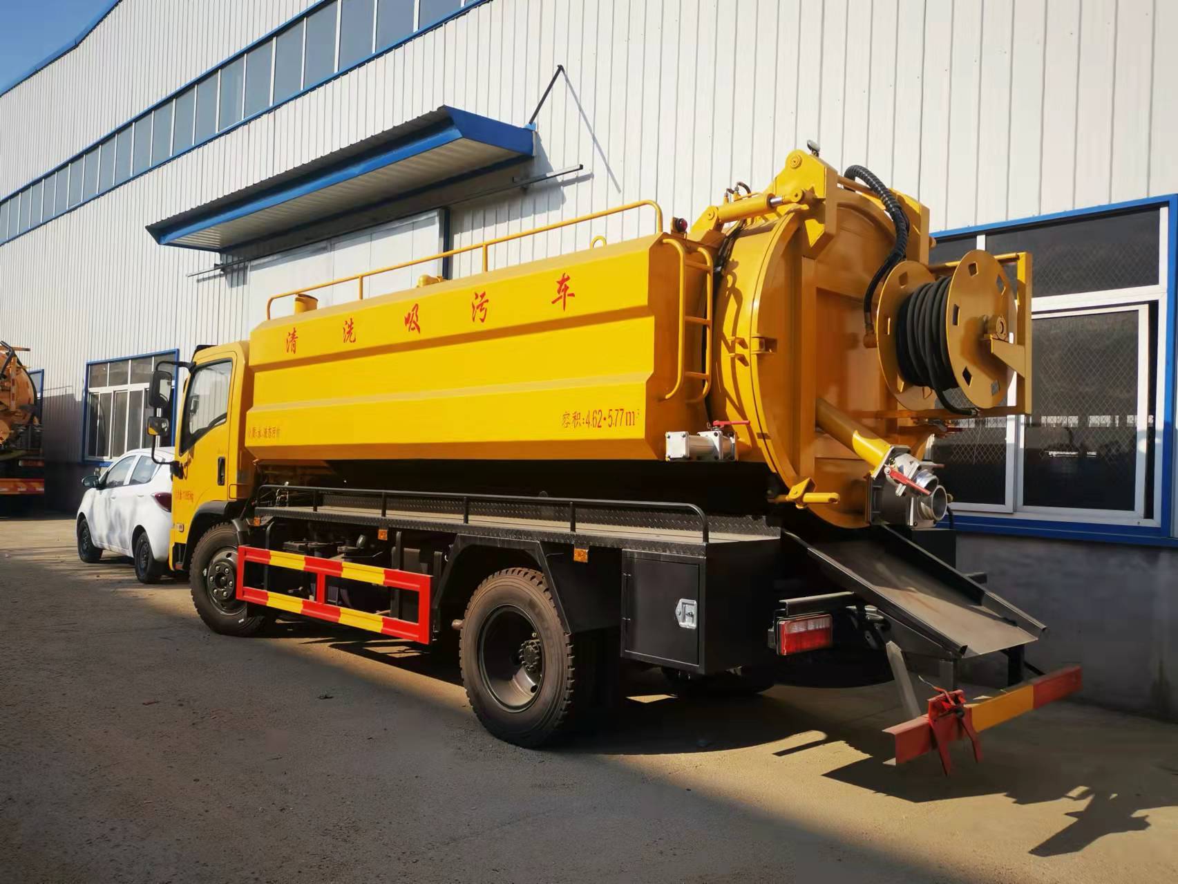

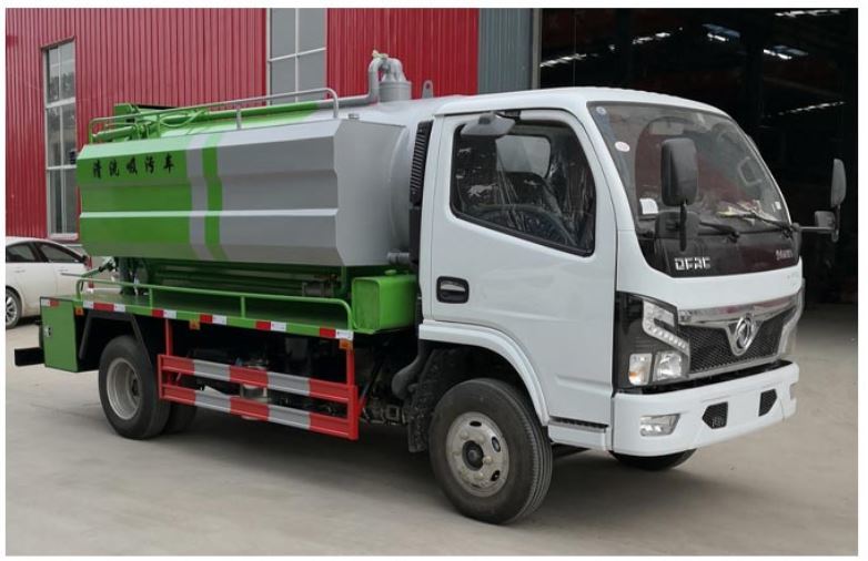


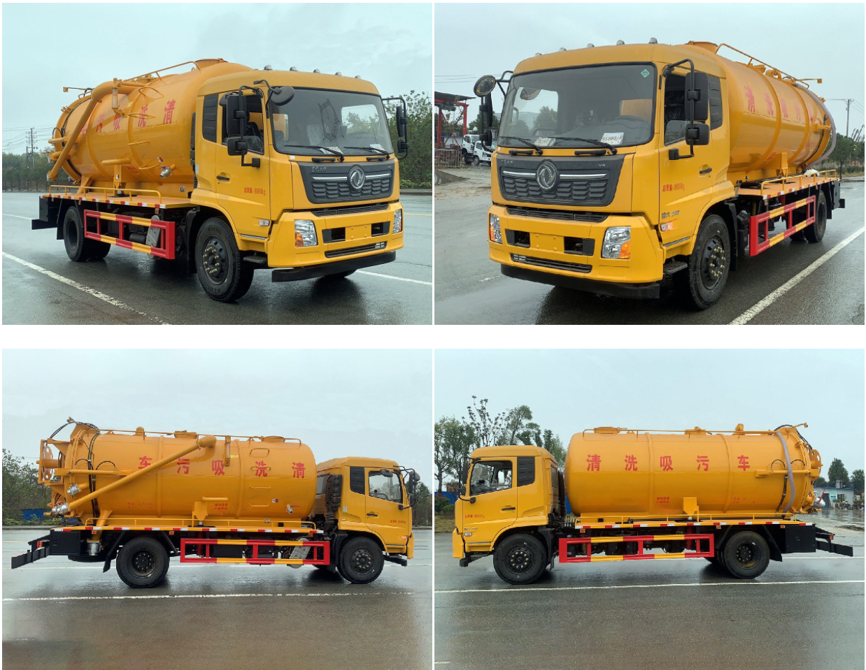

The SZD5075GQW6 features high-pressure cleaning and vacuum suction functions, primarily used for cleaning and clearing sewer pipe networks, and can also be used for the suction and discharge of industrial wastewater.
The high-pressure cleaning function uses a high-pressure water pump to draw water from the water tank. High-pressure water is directed towards the nozzle via a high-pressure hose. The reaction force of the water spraying from the nozzle propels the nozzle and high-pressure hose into the depths of the sewer; simultaneously flushing the sewage sludge, which then flows downstream into the sump.
The vacuum suction function uses an on-board vacuum pump to draw air from the tank to a certain vacuum, creating negative pressure within the tank, causing fecal matter, sewage, sludge, and other liquids from the sump to be automatically drawn into the tank through the pipeline.
The entire vehicle's design, manufacturing, and inspection strictly adhere to national standards and comply with national industry standards, regulations, and safety regulations related to automobiles, tank vehicles, transportation, and environmental protection. The product configuration and materials, outsourced parts, and standard parts used in manufacturing all meet the requirements of relevant national standards. This technical agreement serves as an attachment to the Purchaser's product purchase contract and takes effect simultaneously with the commercial contract, carrying equal legal effect. Supplementary agreements and additional clauses agreed upon by both parties during the contract execution period shall have equal legal effect.
I. Technical Parameters and Configuration
1. Applications and Requirements
This vehicle is mainly used for cleaning and clearing sewer pipe networks, and can also be used for the suction and discharge of industrial wastewater, and internal transfer. It can be licensed and has a tax exemption announcement; this vehicle has the functions of "pumping", "pumping out", "gravity flow", high-pressure cleaning, and clearing sewer pipes;
2. Main Configuration Table
|
Vehicle Configuration Parameters |
Remarks |
|
|
Vehicle Model |
SZD5075GQW6 |
|
|
Batch Announcement |
344th batch (with environmental exemption) |
|
|
Overall Vehicle Dimensions: Length × Width × Height (mm) |
5998×2100×2750 |
|
|
Chassis Configuration Parameters |
||
|
Chassis Model |
Dongfeng National VI EQ1075SJ3CDF |
|
|
Engine Power (hp/kw) |
140/103 |
|
|
Engine Model |
YCY24140-60 National VI (Yuchai) |
|
|
Drive Type |
4X2 Two-axle |
|
|
Engine Displacement (ml) |
2360 |
|
|
Tires |
7.00-R20 steel wire tires/7 sets (including spare tire) |
|
|
Wheelbase (mm) |
3308 |
|
|
Gross Vehicle Weight Rating (kg) |
7360 |
|
|
Vehicle Curb Weight (kg) |
5690 |
|
|
|
|
|
|
Tank Configuration Parameters |
||
|
Wastewater Tank Capacity (m3) |
4 |
Carbon Steel |
|
Clean Water Tank Capacity (m3) |
2 |
Integrated on both sides of the wastewater tank, optional stainless steel material |
|
Tank Material |
6mm/Q235 |
|
|
Maximum Tank Lifting Angle |
39° |
|
|
Wastewater Tank Design Negative Pressure (Mpa) |
-0.1 |
|
|
Maximum Working Positive Pressure in Wastewater Tank (Mpa) |
0.06 |
|
|
Wastewater Tank Design Positive Pressure (Mpa) |
0.25 |
|
|
Tank Lifting and Tipping Angle (º) |
39 |
|
|
Tank Tipping Time (s) |
≤70 |
|
|
Maximum Rear Cover Opening Angle (º) |
91 |
|
|
Control water pumping and sewage discharge operations |
Stainless steel manual ball valve (DN100) |
|
|
|
|
|
|
Loading Operation Configuration Parameters |
||
|
Loading Method |
Negative Pressure Suction |
|
|
Suction Machinery |
Vacuum Pump |
With four-way valve, overflow valve, filter device, added water-sewage intercommunication function, oil-water separator. Equipped with 8-meter steel wire vacuum suction pipe |
|
Vacuum Pump Model |
Suizhou Yifeng |
|
|
Drive Mode |
Transmission PTO |
|
|
Maximum Negative Pressure (Mpa) |
-0.093 |
|
|
Flow Rate (m³/h) |
360 |
|
|
Tank Suction Capacity (m) |
Vertical 9~10 |
|
|
Time to Fill Tank (min) |
≤20 |
|
|
Suction Hose Inner Diameter (mm) |
100 (matched with on-site pipe connector) |
|
|
|
|
|
|
Discharge Operation Configuration Parameters |
||
|
Discharge Method |
1. Positive pressure discharge; 2. Open rear cover and lift for self-discharge |
|
|
Discharge Machinery |
Shared with suction vacuum pump |
|
|
Discharge Hose Inner Diameter (mm) |
100 |
|
|
Hydraulic System Working Pressure (MPa) |
16 |
|
|
Tank Lifting |
Mid-mounted double-cylinder |
|
|
Rear cover opening |
Hydraulic |
|
|
Rear cover locking method |
Mechanical screw |
|
|
Maximum rear door opening angle (º) |
91 |
|
|
|
High-pressure cleaningSystem configuration parameters |
|
|
High-pressure water pump |
PF36/German Pinfu |
|
|
Drive Mode |
Engine rear sandwich power take-off |
|
|
Maximum pressure (mpa) |
24 |
|
|
Flow rate (L/min) |
170 |
|
|
High-pressure hose |
60 meters/DN19 |
|
|
High-pressure nozzle |
10 pieces/DN19 |
|
|
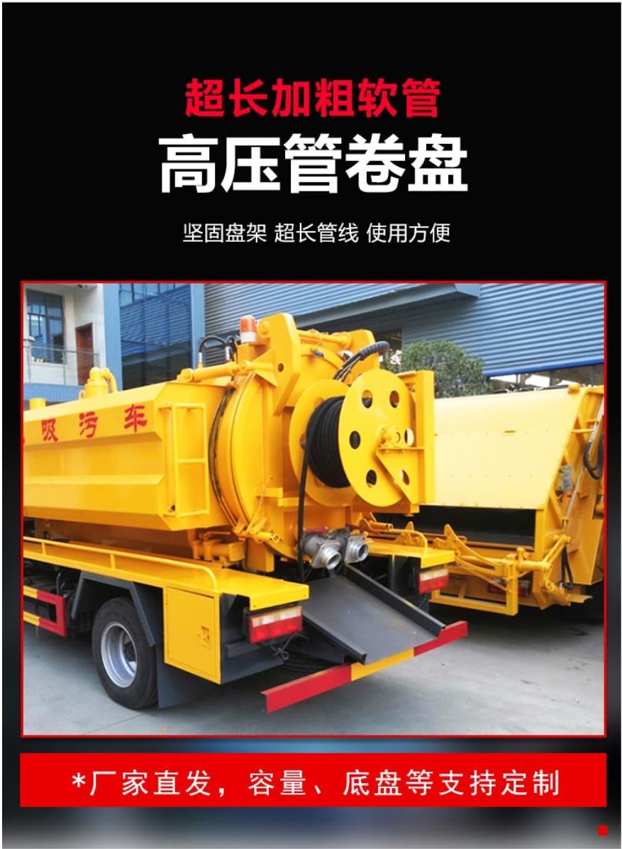
High-pressure hose reel |
Tank rear-mounted, with automatic return |
Optional air-blowing water function (effectively prevents high-pressure pipe freezing and cracking in winter) |
3. Attachment configuration table (per vehicle)
|
On-board attachment configuration table |
||||
|
Serial number |
Specification |
Model |
Quantity/Piece |
Remarks |
|
1 |
Steel wire vacuum suction pipe |
DN100, 8 meters long |
1 piece |
|
|
2 |
Quick connector female end |
DN100 |
1 piece |
|
|
3 |
High-pressure hose |
DN19, 60 meters long |
1 |
High-pressure cleaning (on-board) |
|
4 |
High-pressure nozzle |
DN19 |
10 |
High-pressure cleaning |
|
5 |
Chassis on-board tools |
1 set provided with chassis |
1 |
|
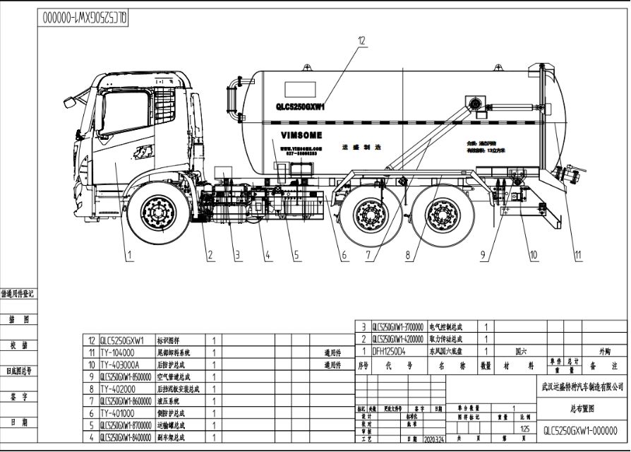
II. Structure and Composition
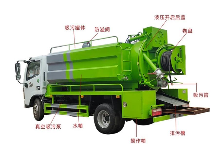
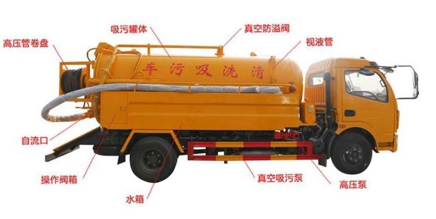
In addition to the vehicle chassis, the suction truck's upper structure includes: clean and sewage tank assembly, power take-off transmission system, pumping and drainage pipeline system, high-pressure cleaning and dredging system, pipe box, side and rear guardrails, and safety protection devices, etc.
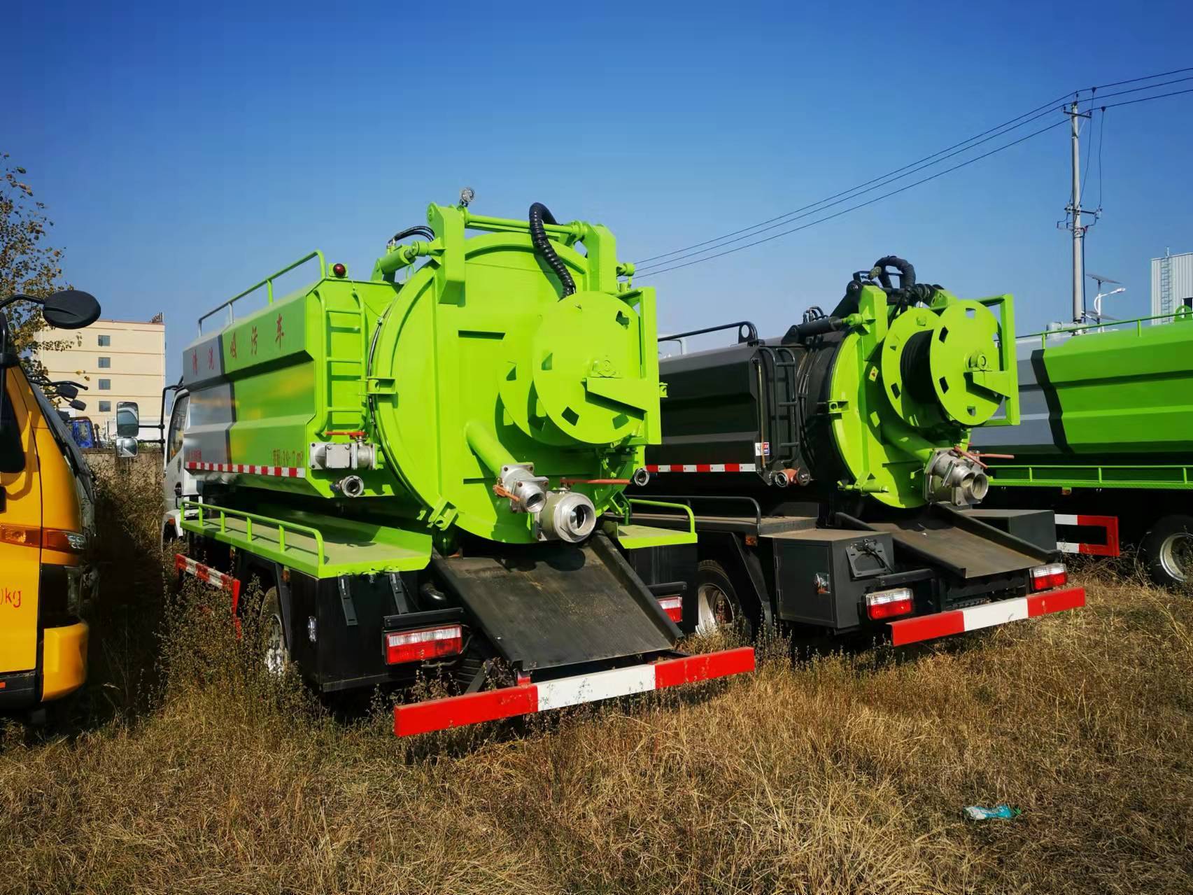
1. Tank Assembly
Circular sewage tank, with clean water tanks on both sides, interconnected through pipelines.
A bottom frame is welded to the bottom of the tank, and it is fixed to the vehicle beam through U-bolts and connecting plates. The tank has reliable strength and rigidity to ensure that the vehicle tank does not deform during operation and pumping operations.
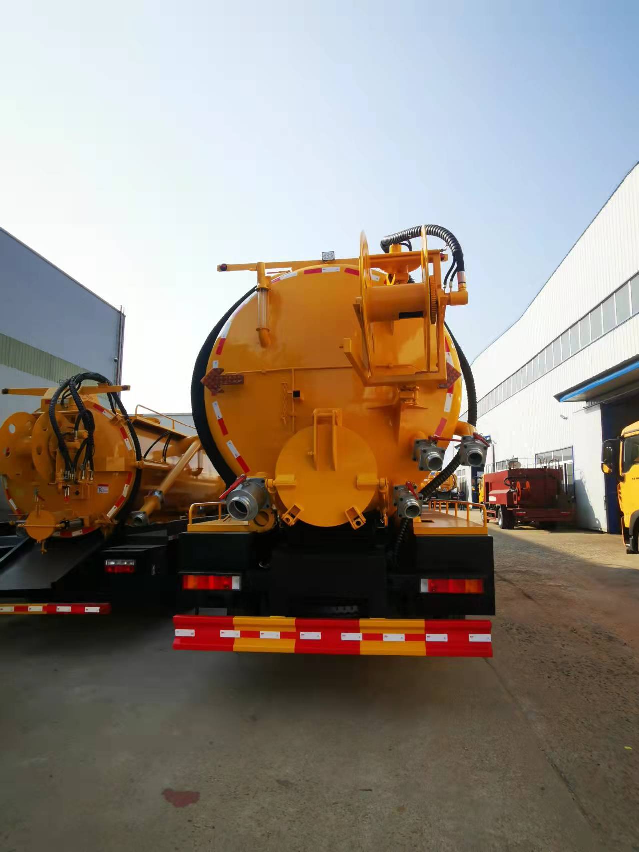
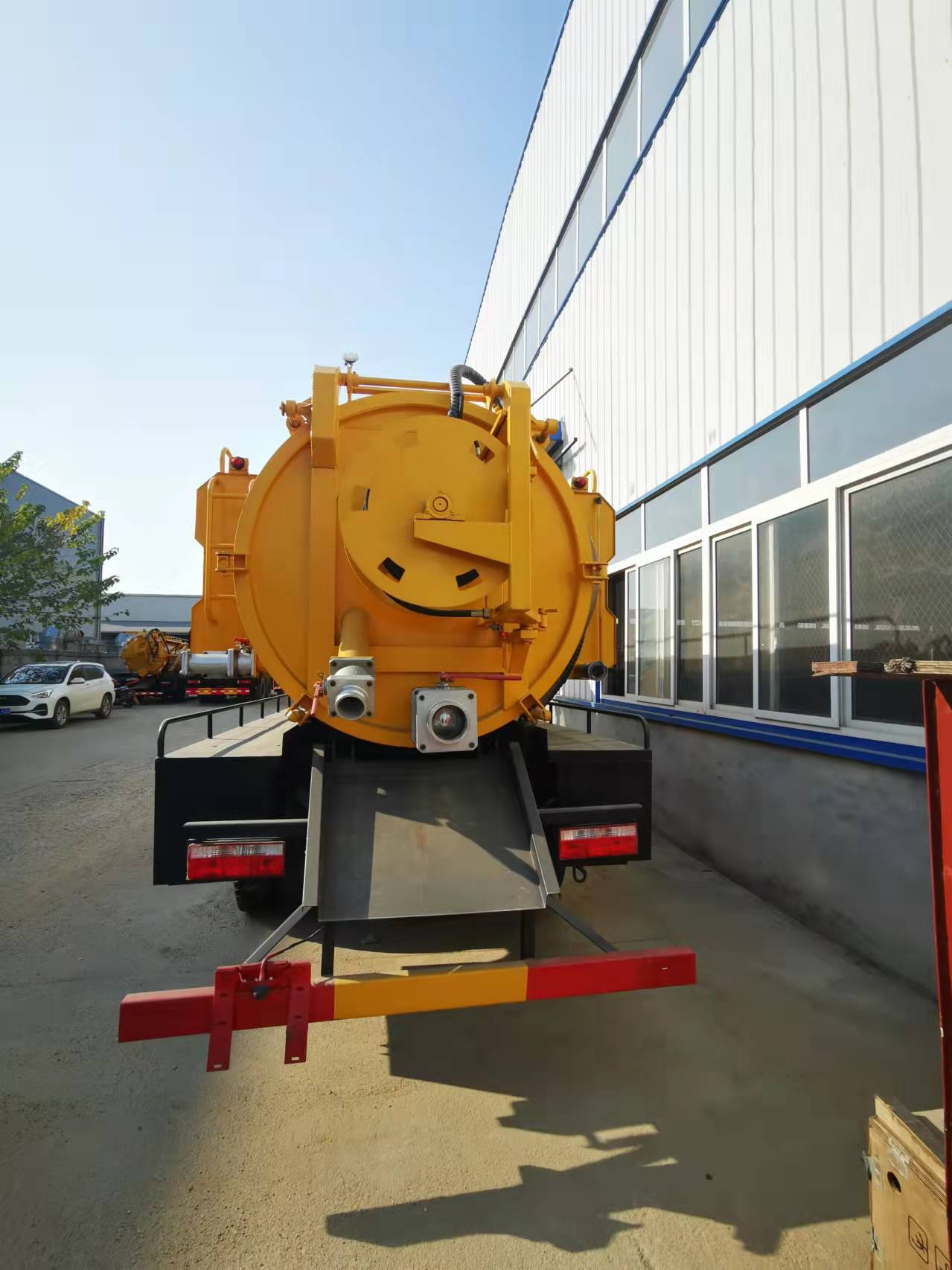
The suction pipe assembly (suction pipe, suction ball valve and quick connector) is installed on the side and rear of the tank, and the suction pipe enters the tank from the top.
The flange ring at the rear of the tank is hinged to the rear cover end cap. The rear cover is fitted with a sealing ring, and the underside of the rear cover is fitted with a DN100 (matched on-site) discharge ball valve and quick connector for connecting the discharge hose. The rear cover is opened and closed by two oil cylinders installed on both sides of the tank. The maximum opening angle of the rear cover is 900. In addition to the two aforementioned opening oil cylinders that also serve as locking devices, the rest are all manually locked with a screw device.
The check valve is installed at the connection between the tank and the inlet and outlet pipes to prevent backflow during charging operation. A full-load alarm device is installed at the front of the tank top.
The tank is mainly used for loading sludge and sewage, and it withstands negative pressure during suction and positive pressure during pressure discharge. The negative pressure design pressure of the tank is "complete vacuum", and the positive pressure design pressure is "0.25 MPa". The tank has reliable strength and rigidity, ensuring that the tank does not deform during suction and discharge operations. The tank and the rear cover, the charging port and the charging cover, and the pipelines are all connected with sealing rings fastened by oil cylinders or bolts, ensuring the airtightness of the tank.
The tank is lifted by two oil cylinders installed on both sides of the tank, and the limit angle of lifting is controlled by a hydraulic limit valve. The maximum lifting angle of the tank is 39 degrees.
2. Power Take-off Transmission System
The power take-off transmission system includes a vehicle power take-off, a transmission shaft, a gear pump driving a vacuum pump, and a high-pressure water pump (see parameter table for details).
3. Pumping and Drainage Pipeline System
3. Pumping and Drainage Pipeline System
The pumping and drainage pipeline is a DN100 steel wire rubber hose, and the interface uses standard quick connectors. Different combinations of ball valves are used to achieve three operating functions: "pump suction", "pump discharge", and "self-flow":
Pump suction:Sewage in the mine shafts of industrial and mining enterprises is pumped into the vehicle tank (see Figure 1 for gas flow direction);

(Figure 1)
Pump discharge:Sewage in the vehicle tank is pumped to the user-specified location (see Figure 2 for gas flow direction);

(Figure 2)
Self-flow:Sewage in the vehicle tank is discharged to the user-specified location without the pump, relying on self-flow through the pipeline or by opening the rear cover (see Figure 3).

(Figure 3)
4. Others
The design and manufacturing of this vehicle conform to the relevant national standards for tank vehicles and motor vehicle safety regulations.
Appendix
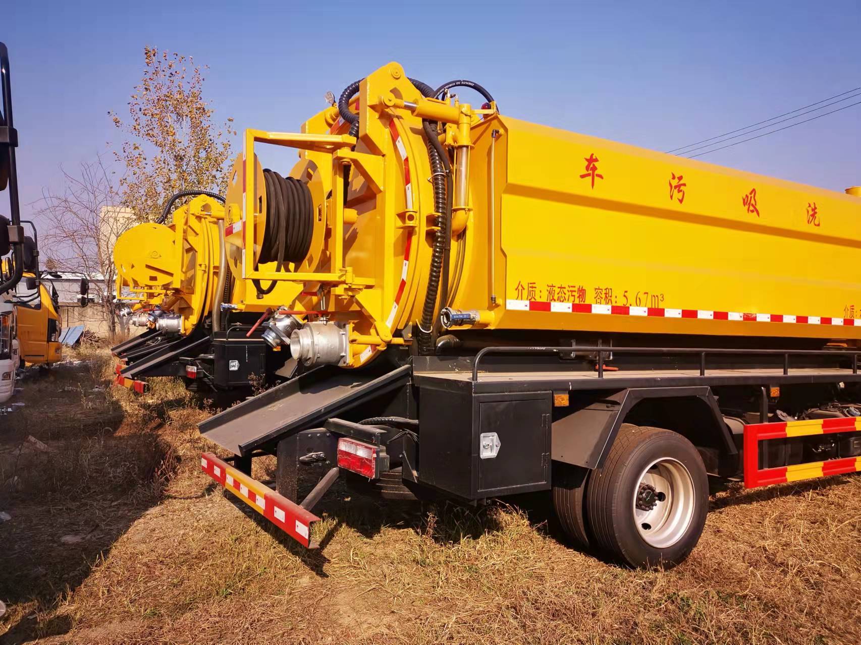
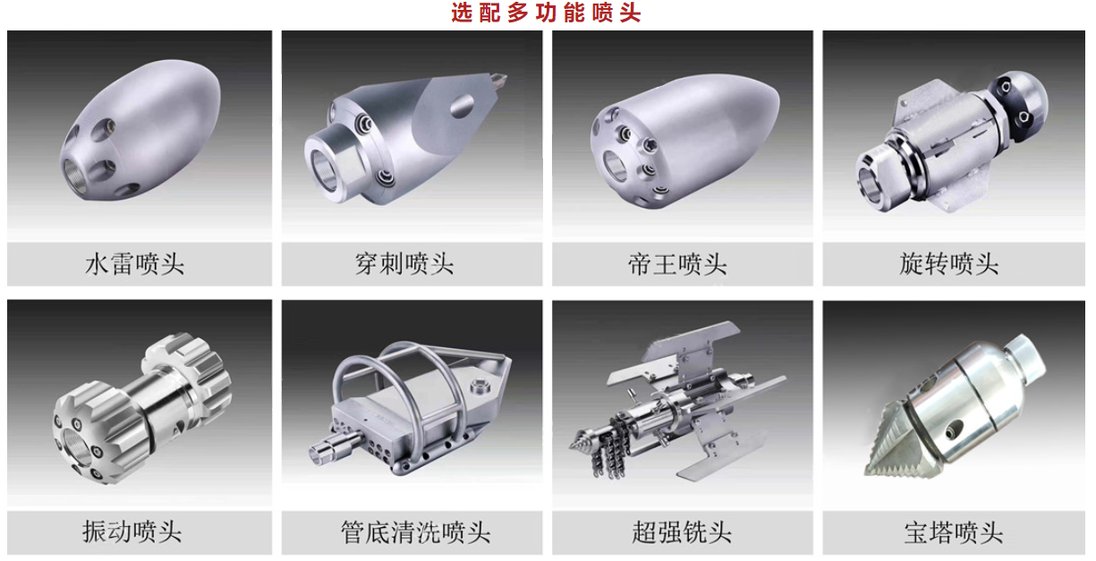
4. High-pressure cleaning and dredging system
This vehicle mainly consists of a type II chassis, water tank, water and oil systems, hydraulic hose reel, high-pressure flushing device, etc. It uses a high-pressure water pump to draw water from the water tank, and the discharged high-pressure water is pressed towards the nozzle through a high-pressure hose. The reaction force of the water spraying backward from the nozzle of the high-pressure nozzle causes the nozzle to enter the depths of the sewer with the high-pressure hose; at the same time, it flushes the sludge in the sewer, allowing it to flow into the downstream sump with the water to achieve the purpose of cleaning and dredging.
5. Others
The design and manufacturing of this vehicle conform to the relevant national standards for tank vehicles and motor vehicle safety regulations.
After-sale Service:
① After the product arrives on site, Party B shall send personnel to the site for handover and cooperate with Party A for acceptance.
② Party B shall provide training to Party A's relevant operators and maintenance personnel (see Appendix for details). The technical training time shall be no less than 2 days (including product structure introduction, on-site operation, maintenance, and troubleshooting).
|
Personnel Training Plan (Appendix) |
|||||
|
Time |
Training Content |
Textbook |
Training Location |
Remarks |
Teacher's Title/Number |
|
Day One |
Structure and Working Principle |
Lecture Notes |
Classroom arranged by user |
Lecturer's Instruction |
After-sales Engineer/1 person |
|
Function and Operation Demonstration |
Product Description |
Vehicle Site |
Lecturer's On-site Demonstration |
After-sales Engineer/1 person |
|
|
Day Two |
Personnel Simulation Operation |
Product Description |
Vehicle Site |
Trainee |
After-sales Engineer/1 person |
|
On-site Operation Demonstration |
Product Description |
Work Site |
Lecturer's On-site Demonstration |
After-sales Engineer/1 person |
|
|
Common Troubleshooting Knowledge Explanation |
Product Description |
Work Site |
Trainee |
After-sales Engineer/1 person |
|
Note: After completing 2 days of training, trainees will undergo a comprehensive theoretical and practical operation assessment. (Trainees must pass the training exam before taking up their posts)
③ One-year Warranty (calculated from the date of product delivery).
④ After delivery of the product, if a malfunction occurs, Party B shall respond within 8 hours after receiving the notification from Party A. After receiving the written notification from Party A, relevant personnel shall propose a solution within 24 hours. For the Central Plains region, personnel will arrive on-site within 48 hours, and for remote areas, within 72 hours. If the malfunction is due to product manufacturing quality issues, during the warranty period, Party B shall be responsible for free repair or replacement of defective parts. For parts installed on the product (vehicle), the after-sales service manual of Party B shall apply; for chassis and other externally purchased parts, the after-sales service terms of the Manufacturer shall apply.
⑤ If a malfunction occurs after the warranty period, Party B will actively provide service.
⑥ If a malfunction occurs, and if it is the responsibility of Party A, Party B will also actively take measures and cooperate to provide Party A with technical services and guidance to ensure the normal use of the contracted product.
⑦ Party B's service hotline Tel: 027-88866833. Party A can call this hotline if they encounter any problems during the use of the product.
III. Appendix
Key words:
罐体
通过
管道
高压
后盖
具有
清洗
功能
作业
Previous
Next
MESSAGE
Message consultation


Address: 528 Dihou Street, Baishazhou Avenue, Wuchang District, Wuhan City, Hubei Province (zip code 430065)
 027-88866812

 3992538510@qq.com
 Online Message
Copyright: Wuhan Yunsheng Special Vehicle Manufacturing Co., Ltd.
The site supports IPV6SEO Tags