

Sewage suction truck
Classification
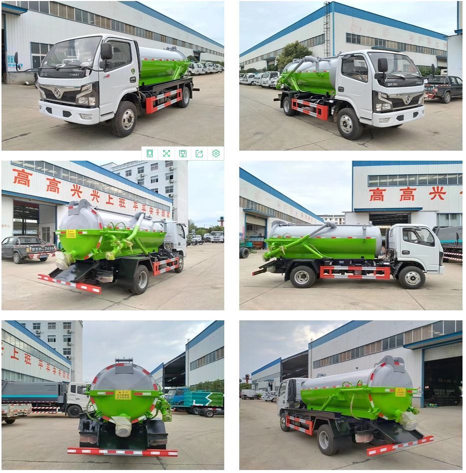
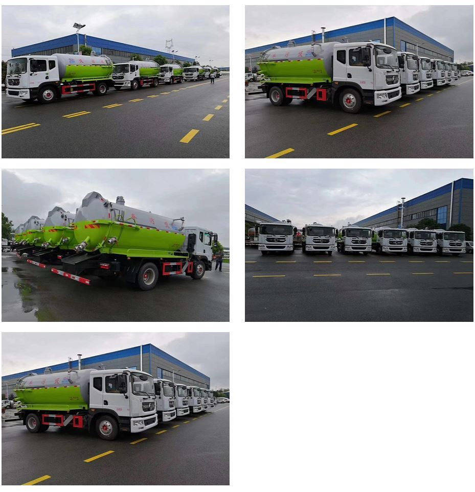
Sewage suction truck
Product Introduction
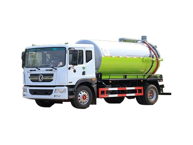

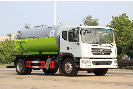


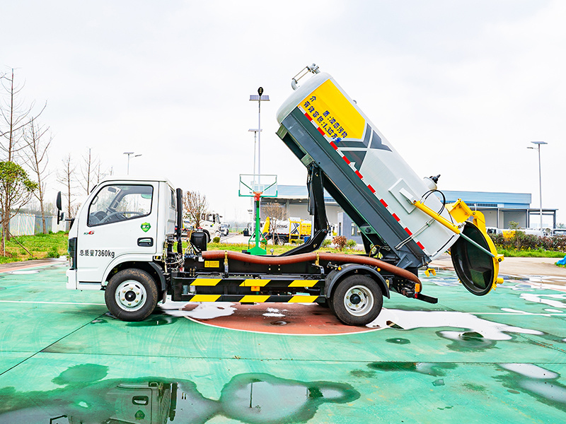
The QLC5250GXW1 suction truck is ideal for suctioning tar sludge water.
I. Technical Parameters and Configuration
1. Applications and Requirements
This vehicle is mainly used for the suction and discharge of wastewater in factories and mines, for intra-factory transportation, can be licensed, and has an exemption from vehicle purchase tax announcement; this vehicle has three operation functions: "pump suction", "pump discharge", and "self-flow";
2. Main Configuration Table
Vehicle Configuration Parameters | Remarks | |
Vehicle Model | QLC5250GXW1 |
|
Batch Announcement | Under Application |
|
Overall vehicle dimensions: Length × Width × Height (mm) | 8200×2500×3450 |
|
Chassis Configuration Parameters | ||
Chassis Model | Dongfeng DFH1250D4 |
|
Engine power (hp/kw) | 290/213 |
|
Engine Model | D6.7NS6B290 National VI |
|
Drive Type | 6X2 |
|
Engine displacement (ml) | 6700 |
|
Tires | 11.00R20 / 11 sets |
|
Wheelbase (mm) | 4350+1350 |
|
Chassis GVW (kg) | 25000 |
|
Vehicle Curb Weight (kg) | 13000 |
|
|
|
|
Tank Configuration Parameters | ||
Tank effective volume (m3) | 13 |
|
Tank inner diameter (mm) | 1700 |
|
Tank material | 6mm/Q235 |
|
Head type | Spin-formed butterfly head |
|
Head material | 6mm/Q235 |
|
Maximum tank lifting angle | 39° |
|
Maximum working negative pressure in tank (mPa) | Vacuum Pump |
|
Tank design negative pressure (Mpa) | -0.1 | |
Maximum working positive pressure in tank (Mpa) | 0.06 | |
Tank design positive pressure (Mpa) | 0.25 | |
Tank lifting and tilting angle (º) | 39 | |
Tank tilting time (s) | ≤70 | |
Maximum rear cover opening angle (º) | 91 | |
Control water suction and sewage discharge actions | Stainless steel pneumatic ball valve | |
|
| |
| Loading Operation Configuration Parameters | ||
Loading method | Negative pressure suction |
|
Suction machinery used | Vacuum Pump |
|
Vacuum pump model | 50QZXDH-68-7000 | Hangzhou Weilong |
Tank suction capacity (m) | Horizontal 30, Vertical 8 |
|
Time to fill a truck (min) | ≤20 |
|
Suction hose inner diameter (mm) | 100 (matched with on-site pipe joints) |
|
|
|
|
Discharging Operation Configuration Parameters | ||
Discharging method | 1. Positive pressure discharge; 2. Open rear cover and lift for self-discharge |
|
Pressure discharge machinery used | Shared with suction vacuum pump |
|
Sewage discharge hose inner diameter (mm) | 100 |
|
Hydraulic system working pressure (MPa) | 16 |
|
Tank lifting | Side top double cylinder |
|
Rear cover opening | Double cylinder |
|
Rear cover locking method | Mechanical screw |
|
Maximum rear door opening angle (º) | 91 |
|
3. Attachment Configuration Table (per vehicle)
On-board Attachment Configuration Table | ||||
Serial number | Specification | Model | Quantity/Piece | Remarks |
1 | Suction and discharge rubber hose | DN100 8 meters long | 1 piece | |
2 | Quick connector female end | DN100 | 1 piece | |
3 | Chassis on-board tools | 1 set provided with the chassis | 1 |
|
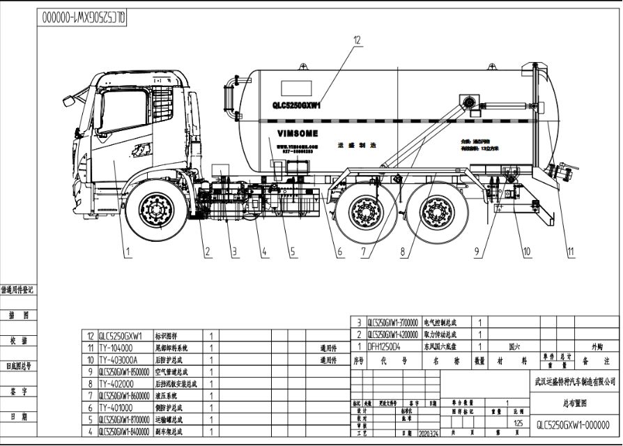
II. Structure and Composition
In addition to the vehicle chassis, the suction truck's superstructure includes: tank assembly, power take-off transmission system, suction and discharge pipeline system, pipe box, side and rear guardrails, and safety protection devices, etc.
1. Tank assembly
The tank is a "cylindrical" container with internal baffles welded inside to divide the tank into compartments, reducing the impact of wastewater fluctuations and inertia on the compartment walls during vehicle travel. Components include the cylinder, end caps, and baffle plates. A water level indicator is installed above the rear end cap. Lifting lugs and a manhole are also installed on the tank top.
A bottom frame is welded to the bottom of the tank, and it is fixed to the vehicle's main beam via U-bolts and connecting plates. The tank has reliable strength and rigidity to ensure that it does not deform during vehicle operation and suction/discharge operations.
The suction pipe assembly (suction pipe, suction ball valve, and quick connector) is installed on the side of the tank, with the suction pipe entering the tank from the top.
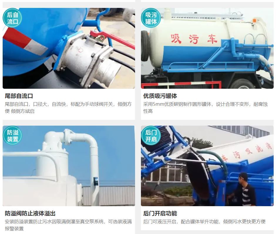
The flange ring at the rear of the tank is hinged to the rear end cap. A sealing ring is installed on the rear cover, and a DN80 or DN100 (depending on site configuration) discharge ball valve and quick connector are installed on the underside of the rear cover to connect the discharge hose. The rear cover is opened and closed by two cylinders installed on either side of the tank. The maximum opening angle of the rear cover is 90°. In addition to the two opening cylinders, which also act as locking devices, the rest of the rear cover is locked using a screw-type manual locking device.
A check valve is installed at the connection between the tank and the inlet/outlet pipes to prevent backflow during charging operations. A full-load alarm is installed at the front of the tank top.
The tank is mainly used for loading sludge and wastewater, and it withstands negative pressure during suction and positive pressure during discharge. The tank's negative pressure design pressure is "full vacuum," and the positive pressure design pressure is "0.25 MPa." The tank has reliable strength and rigidity, ensuring that it does not deform during suction and discharge operations. All connecting surfaces, such as the tank and rear cover, charging port and charging cover, and pipes, are sealed with sealing rings secured by cylinders or bolts to ensure the airtightness of the tank.
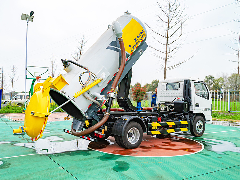
The tank is lifted by two cylinders installed on either side of the tank. The maximum lifting angle is controlled by a hydraulic limit valve. The maximum lifting angle of the tank is 39 degrees.
2. Power Take-Off (PTO) Transmission System
The PTO transmission system includes a vehicle PTO, a transmission shaft, and a gear pump driving a vacuum pump (see parameter table for details).
3. Suction and Discharge Piping System
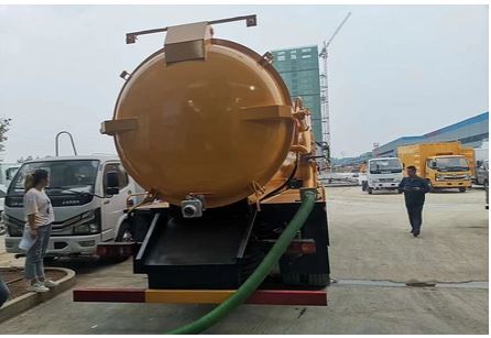
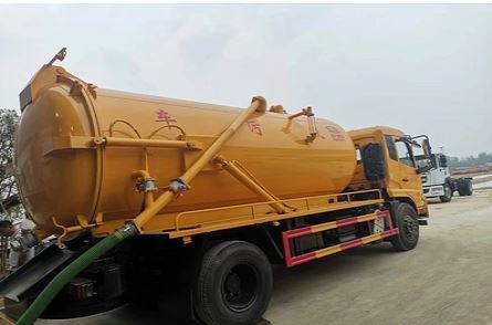
The suction and discharge piping is a DN100 steel wire reinforced hose with standard quick connectors. Different combinations of ball valves allow for three operating modes: "pump suction," "pump discharge," and "gravity flow":
Pump Suction:Wastewater from mine shafts is pumped into the tank (see gas flow direction in Figure 1).

(Figure 1)
Pump Discharge:Wastewater from the tank is pumped to the designated location (see gas flow direction in Figure 2).

(Figure 2)
Gravity Flow:Wastewater from the tank is discharged to the designated location by gravity flow through the pipes or by opening the rear cover (see Figure 3).

(Figure 3)
4. Other
The design and manufacture of this vehicle comply with national standards for tank vehicles and motor vehicle safety regulations.
Appendix: Figures
Key words:
罐体
后盖
配置
作业
抽吸
正压
真空泵
底盘
装在
Previous
Next
MESSAGE
Message consultation


Address: 528 Dihou Street, Baishazhou Avenue, Wuchang District, Wuhan City, Hubei Province (zip code 430065)
 027-88866812

 3992538510@qq.com
 Online Message
Copyright: Wuhan Yunsheng Special Vehicle Manufacturing Co., Ltd.
The site supports IPV6SEO Tags